The Trackball Mount
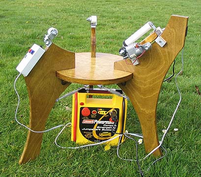 This is the part of the
trackball system that makes it track. The basic principle of the whole
works is to rest the spherical bottom of the telescope against an axle
that points at the celestial pole, and to rotate the axle so the sphere
turns once a day--exactly counteracting Earth's rotation. The axle is
mounted on a shuttle that can be moved along an arc, allowing adjustment
for the viewer's latitude.
A sphere needs at least three points of support to hold it in place.
The axle is one of those points. I tried Teflon glides for the other
two, but at the incredibly slow speed of the ball's rotation, even
Teflon proved too sticky. Rather than track smoothly, the scope would
lurch forward, then pause, then lurch, then pause. Wax helped, but then
the ball's balance became supercritical. There's undoubtedly a happy
medium somewhere, but I gave up and went to roller bearings. That turned
out to be a good move. Roller bearings allow frictionless motion in the
right direction and resist motion in other directions, which actually
helps force the scope to track more precisely as well as more smoothly.
(No, they don't swivel, and yes, the ones in the photo are really angled
in the correct direction for my latitude. See below for details.)
A little experimentation showed that PVC pipe provided the right
amount of friction to keep the ball in place, yet let it slew smoothly
with just a light push.
The center disk is just a simple plywood round purchased pre-cut
from a lumber store. The legs were all cut from one 2' x 2' piece of
plywood. I cut notches in the legs so they would fit nice and tight over
the disk, then used chair-stiffening brackets underneath to stiffen them
even further (just visible under the left side of the disk). I still had
a bit of vibration, so I later added the turnbuckle tensioners.
I keep meaning to drill some holes in the disk for eyepiece storage
while I'm observing, but never got around to it. Good thing, actually.
The modification below would have blocked the eyepiece holes anyway.
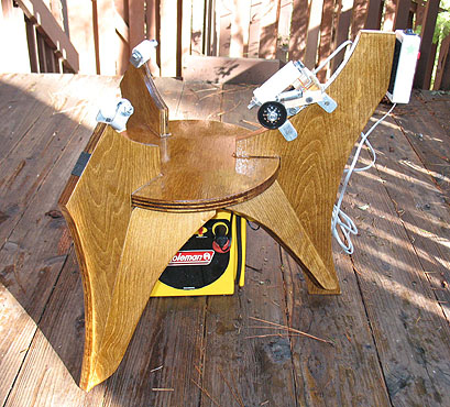 A BETTER LEG BRACING
SYSTEM: The mount as built above allows some vibration, probably from
the long skinny legs and the relatively short triangles created by the
turnbuckles. I built a second trackball for my wife, Kathy, and braced
the legs with wooden gussets, and that really stiffened it up. The
settling time went from 6 seconds to 3. I'm also experimenting with
sorbothane anti-vibration pads under the feet. The right thickness will
get the settling time down to 1-2 seconds, at the cost of a little
sponginess to the entire scope when you slew it. Sorbothane knocks down
the short-period vibration almost completely, though. You can buy a
whole sheet of the stuff -- a lifetime supply -- at Edmund Scientific.
I also made the drive axle a little larger in diameter and used
roller-blade bearings rather than the bic pen design on my first scope.
It's nearly frictionless, which allowed me to use a lighter-duty motor,
but otherwise the design is similar. I've described both axle designs
below.
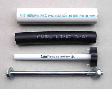 The axle
The axle is pretty simple: On my first trackball I used a carriage
bolt, some washers, a Bic pen barrel, a hose, and a piece of PVC pipe. I
had to ream out the pipe to get the hose to fit.
The gear is from a hobby shop. It's the drive gear for a
radio-controlled car, and costs about $2.50. Drill out the hub so it
fits snugly over the pen barrel, and drill a couple of tiny holes in the
spokes for equally tiny brads to pin it to the pipe so it will actually
turn the axle instead of just spin in place. In the S&T
article I said to pin the gear to the hose, but I later realized there's
too much flex that way. Pin it to the pipe. (You could also glue it if
you want.)
Wax the bolt before you slip it inside the pen barrel. I just ran a
birthday candle up and down it a few times.
The bracket that holds the axle (see below) is a piece of 3/4" x
3/32" bar stock bent into a shallow "U" and screwed to a block of wood.
Leave room for the worm gear (a 3/8" bolt) to clear the bracket. (If you
use a different gear than what I used, you may need a different size
bolt to mesh with the teeth.)
The washers keep things from slipping apart and provide spacers so
the axle fits snugly in the bracket. Any play there will become slop in
declination when you're using the scope.
You can remove the lettering on the pipe with a simple rubber eraser.
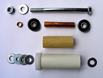 NEWER AXLE DESIGN: On my later axles
I used roller blade bearings instead of a Bic pen barrel. It's a little
more complicated, but well worth the trouble. The roller blade bearings
are nearly frictionless, which means you can use a smaller drive motor.
The copper tubing allows you to tighten the bolt without squeezing
the bearings together. The wooden dowel keeps the PVC pipe from buckling
under the weight of the telescope. (It's probably not necessary, but I
did it just in case.) The dowel is drilled out to a diameter a little
larger than the copper tube, so the dowel can rotate without rubbing on
the tubing. The tiny piece of copper tube is to keep the washers from
pushing the gear into the bearing and creating friction there. Drill out
the center of the gear so it doesn't touch the copper spacer (just like
the dowel doesn't touch the long piece of tubing). The gear is glued to
the outer (PVC) pipe. Do this after you assemble everything! You want
the gear to be absolutely centered. It shouldn't wobble at all when you
spin the axle, or the worm gear will tighten up on the high side and
loosen on the low side.
The washers are smaller than the bearing diameter and keep the
bearing faces from rubbing on the metal bracket that holds the whole
works in place. The PVC pipe had to be a little larger than the first
axle so it could hold the bearings. Even so I had to hollow out the
inside a bit to make them fit.
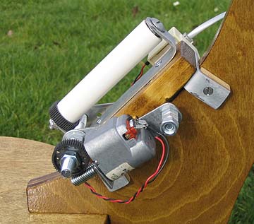 The motor
The ball has to turn once per day. If you have a 16" ball and a 7/8"
axle, that means your axle has to turn 18.28 times per day. A 50-tooth
drive gear means your worm gear needs to turn 914 times per day, or
0.635rpm. It's hard to find a motor that turns that slowly, so I made a
second worm gear that brought the motor speed up to 30 rpm. It's a lot
easier to find 12-volt DC motors in that range. I bought one that was
rated for 20-45 rpm so I could tweak the tracking speed quite a ways if
my calculations were off. (I got mine from Techmax,
which sells salvaged motors. Jameco
also has a good selection of new motors.)
You could undoubtedly use a step motor if you want. I went with a
simple DC gear motor because the circuitry is so much simpler. A
variable resister between the motor and the battery is all you really
need for a speed control. I got a little fancier, but not a whole lot
more so. (See circuit diagram below.)
I had to drill a hole in the second worm gear (i.e. another 3/16"
bolt) so it could fit over the motor shaft. I had a heck of a time
getting the hole centered until I realized I could put the bolt in a
drill press and lower it onto a stationary drill bit. Perfectly centered
hole! Epoxy it onto the motor shaft, and occasionally run the motor
while the glue is setting so you can detect (and correct) any wobble.
This worm should be as perfectly centered on the motor shaft as you can
get it. A little wobble won't matter, but too much will give you a
periodic tracking error.
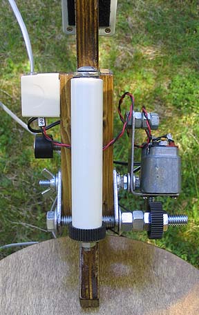 At
first I mounted the motor on a pivot so the weight of the motor would
hold the worm against the drive gear. That turned out not to be quite
enough weight, so I added a bolt and a few nuts for more weight on the
back of the motor. The pivot is on the same shaft that holds the other
worm gear's mounting brackets, which explains that thicket of nuts and
washers between the motor and the shuttle in the photo at right. Later I
gave up on that and added the spring-loaded idler below. It pushes the
motor's worm-gear shaft against the drive gear, and that works much
better than simply adding weight to the back.
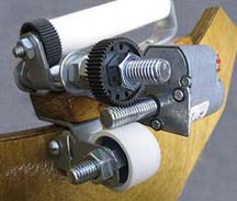 The worm gear that drives the PVC axle is held
into place by two more pieces of 3/4" x 3/32" bar stock. The angle of
the bar stock allows the worm to be adjusted up and down so it meshes
smoothly with the drive gear's teeth. I leave a little play in those
gears, because the weight of the telescope compresses the axle and
tightens them up.
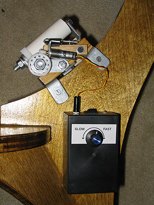 For my next two scopes I used tiny gear motors that I
also got from Techmax.
I was hoping these motors would run quieter than the first one, but
they don't. If anything, they're louder. I had to isolate them with
sorbothane to keep them from vibrating the whole mount like a big
speaker cabinet, but that did the trick and you can barely hear them now.
They do pull much less current, though (about 10-15 milliamps), so I
don't need a big battery to run the drive anymore. I run it on a set of
6 AA batteries in the black box Velcroed to the leg below the motor
shuttle, and figure I can get 20-30 nights of observing on a set of
batteries. I used the same basic electrical circuit as described below,
minus the momentary switches, which I never used on the original scope.
This system has one great advantage: it's all attached to the mount so
you have fewer things to carry. (And no hand controller wires to trip
over in the dark.)
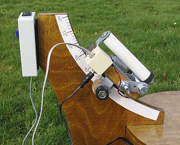 Latitude adjustment
The latitude arc should be concentric with the sphere, so when you
move the axle shuttle up or down, the sphere stays put. You don't have
to be overly finicky about this; just get it close. (Don't use the same
radius as the sphere for this arc! The radius of the arc has to be
bigger than the radius of the sphere by the thickness of the
axle-shuttle combination.)
My shuttle uses two pads on the back side (visible four pictures
above) and one on this side with a screw-down clamp to hold it in place. 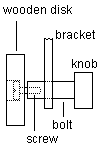 Use wood for the pads, rather
than rubber, or you'll get a lot of vibration in the scope. The clamp is
just a bolt with a wooden disk on the end of it. I got fancy and drilled
a hole in the end of the bolt so I could screw the disk onto it. It's
harder than I thought to tap threads into a bolt!
The knob is just a nut snugged up to the bolt head and both of them
covered with a piece of rubber hose.
I made a power distribution box out of an old telephone adapter.
Power goes into the box from a 12-volt battery below, then up the phone
cord to the hand controller and back to the motor.
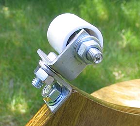 The other two bearings
The other two bearings are just idlers. They let the ball move
without friction in the direction of tracking motion, and they provide
just enough grip to constrain that motion to the angle you set them at.
They're made of PVC pipe couplings with rollerblade bearings inside.
Rollerblade bearings are cheap--about $1.25 each--and you can use a
5/16" bolt for an axle. There are a couple of nuts down inside to keep
the edge of the PVC from rubbing on the bracket. The angle brackets are
made from the same 3/4" x 3/32" bar stock as the drive axle mount. I
made mine adjustable in two axes, but after using the scope a while I
realize that I only needed the top adjustment. See a better design below.
The pipe couplings have to be reamed out a little for the bearings
to fit. You don't need the whole coupling--half or 3/4 of it will do.
The main reason to have it at all is to give the ball a nice slick PVC
surface to ride on, and to make that surface wide enough that the edge
of the bearing can't dig into the paint. (Rollerblade bearings alone are
way too narrow.)
The bearings don't have to be positioned at any particular spot on
the sphere, but bear in mind that the farther up they are, the more
they'll get in the way when you point the scope toward the horizon. I
made mine so I could tilt the scope horizontal without dropping off the
bearings, but high enough so I wouldn't push the scope off the mount
when I was slewing it.
The angle of the bearing is determined by your latitude. More on
that below.
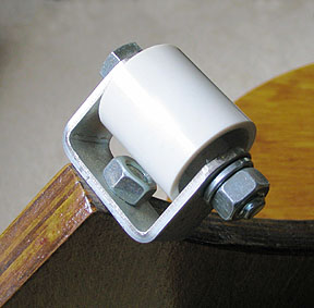
A BETTER BEARING MOUNT: The
above bearing mount design allowed too much vibration, so in subsequent
scopes I've used a U-shaped bearing bracket that's way more
stable. There's still just one rollerblade bearing centered inside, with
a couple of nuts spun onto the bolt on either side to act as spacers to
keep the edge of the PVC from rubbing on the bracket. You can see that
the whole thing mounts directly on top of the wooden leg, rather than
hanging out in space like my first design. This is a much better design!
Go with this one.
If the ball doesn't rest on the middle of the bearing, you can put a
shim under one side of the bracket.
DECLINATION CONTROL: It turns out
there's an easy way to add declination control to a trackball. Thanks go
to Pierre Lemay for this idea.
If you mount the idler bearings so they can be moved toward or away from
the drive axle (actually I think moving them toward or away from the
celestial pole would be more direct) their motion will force the ball to
roll up or down the axle, which translates into motion in the
declination axis. You may need omnidirectonal idler bearings in order to
prevent the ball from skidding. You could also get declination control
by moving the drive axle in or out (being careful to maintain its polar
alignment while it moves). Be careful to limit the range so you don't
push the ball off the idlers!
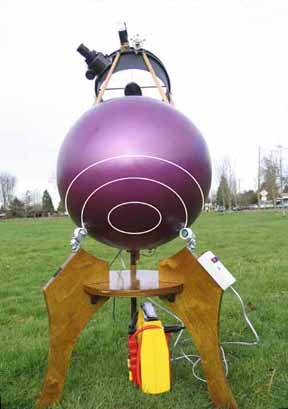 Bearing angle
You might think that the two idler bearings should be angled so they
roll more horizontally. I thought so, too, until I watched the way the
ball skidded across them. At my latitude (44 degrees north), the
bearings need to be oriented almost vertically.
Why is this? Look at the photo to the left. Think of the ball as a
globe that spins just like the Earth does (but in the opposite
direction). I've pointed the telescope at the celestial pole to make
this easier to visualize, and I've drawn latitude lines on the ball to
show where something touching it would track when the ball spins. The
bearings need to roll along those latitude lines.
Now imagine taking the telescope to Alaska, where the celestial pole
is much higher in the sky. The scope will be angled much higher, so the
bearings will need to "toe in" a ways to continue tracking lines of
latitude. Go to Hawaii and you get the opposite effect: the celestial
pole is practically on the horizon, so the bearings need to toe out in
order to follow the latitude lines.
Of course it doesn't really matter where the scope is pointed, since
the surface is a sphere. As far as the drive is concerned, it's just
spinning a globe along the celestial axis no matter how that globe is
oriented.
The easiest way to figure the correct bearing angle for your
latitude is to set up the scope with the drive axle aligned to the pole
and just watch the surface of the globe move past the bearings. Adjust
them so they're rolling rather than skidding, and you've got it.
Another way to look at it is to figure where the axis of rotation
sticks out the bottom of the ball (it's the center of that target in the
photo), and aim the axles of the idler bearings at that point.
The power/control box
 For my first scope I made a hand
controller. It seemed like a good idea at the time. I thought it would
be useful to be able to speed up or slow down the tracking so I could
center objects in the eyepiece, but after using the scope a while I
realized that the fast and slow buttons weren't all that useful. The
scope is so easy to nudge manually that it's simpler to just do that if
you need to center an object. I hardly ever used the variable speed
control, either. Once it's set, it's pretty much good. So I redesigned
the whole power/control setup to what you see here, and redesigned the
circuitry inside the box.
It's pretty simple. It's got an on/off switch on top, a
potentiometer to adjust the tracking speed, an LED to indicate when the
power is on, and a set of six AA batteries. I put a power socket on the
side to let me plug in a 12-volt jumpstart battery, and I put a
potentiometer in series with that to drop the voltage down to match the
internal battery pack so the motor will run at the same speed whether
it's runing on the internal 9-volt battery pack or the external 12-volt
battery.
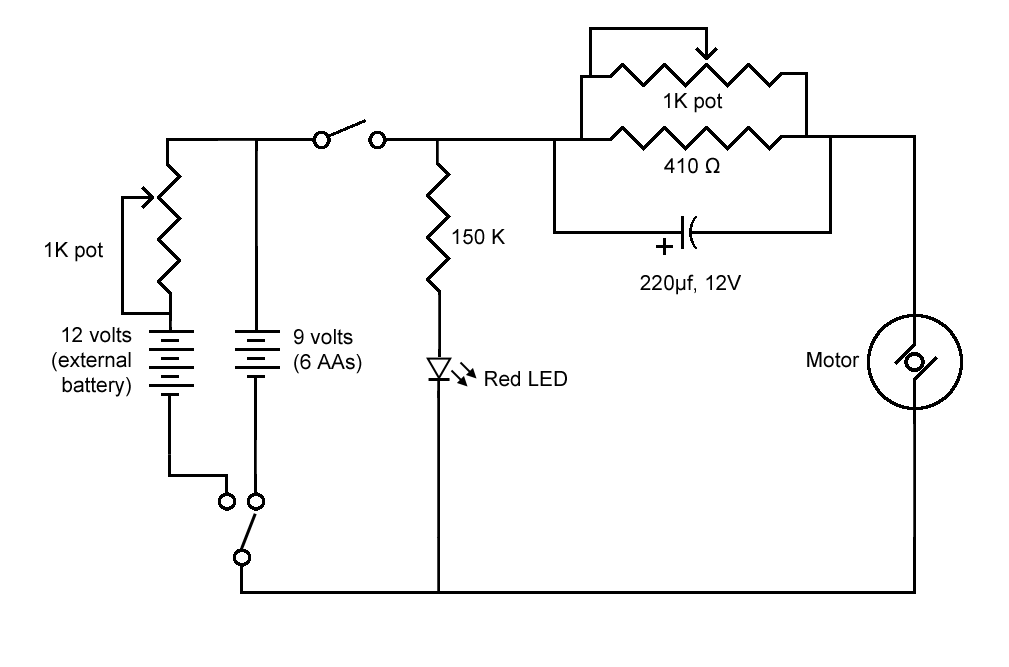 The
circuit is fairly straightforward: Power goes from the battery (either
internal or external) through the potentiometer to the motor. I wired
the potentiometer in parallel with a fixed resistor so the pot wouldn't
have to take all the current going to the motor, but at 10-20 milliamps
I doubt if that was necessary. The electrolytic capacitor provides a
little boost to start the motor when it's cold.
The 150K resistor in series with the LED is there to dim the LED
down to a faint glow. You just need enough light to know it's on; not
enough to be distracting. I sanded the top of the LED to diffuse it
further.
I put everything in a plastic project box and Velcroed it to the
mount underneath the motor. The AA batteries will power the motor for
many, many hours. I can go two or three years on a set of batteries, and
I use this telescope a lot.
Click on the circuit diagram for a larger image.
That's pretty much the mount. I've included a few paragraphs on the
introductory page about how to use a trackball . Here's a direct link to that discussion.
Click here to go to
the discussion of the optics.
Click here to go back to the
trackball front page.
Click here to go back to
Jerry's home page.
 This is the part of the
trackball system that makes it track. The basic principle of the whole
works is to rest the spherical bottom of the telescope against an axle
that points at the celestial pole, and to rotate the axle so the sphere
turns once a day--exactly counteracting Earth's rotation. The axle is
mounted on a shuttle that can be moved along an arc, allowing adjustment
for the viewer's latitude.
 The motor
 Latitude adjustment
 Use wood for the pads, rather
than rubber, or you'll get a lot of vibration in the scope. The clamp is
just a bolt with a wooden disk on the end of it. I got fancy and drilled
a hole in the end of the bolt so I could screw the disk onto it. It's
harder than I thought to tap threads into a bolt!
 Bearing angle